Power Losses in Transformer
Transformer Losses
What are transformer losses?
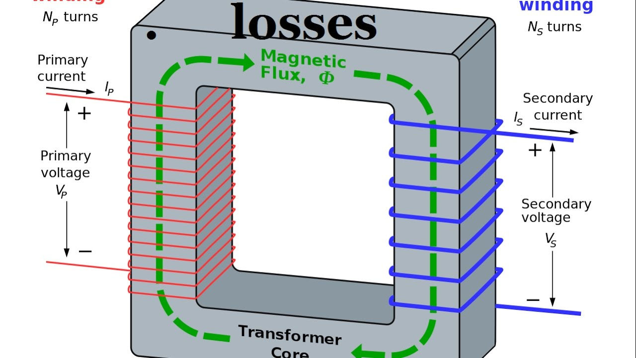
Transformer losses are caused by an electrical current flowing in the coils and by the alternating magnetic field in the core. Losses associated with the coils are called load losses, while losses caused in the core are called no-load loss. In any electrical system, 'loss' can be described as the difference between input and output power. The electrical transformer is a static device, and so there are no mechanical losses (such as winding or friction losses). Transformers consist only of electrical losses (iron losses and copper losses).

Core and Iron Losses
- The core or iron losses consist of hysteresis and eddy current losses and occur in the transformer core due to the alternating flux.
- These can be determined by an open-circuit test.
- Iron or Core losses, Pi = Hysteresis loss + Eddy current loss = Constant losses
- The hysteresis loss can be minimized by using steel of high silicon content.
- The eddy current loss can be reduced by using a core of thin laminations.
- These losses occur in both the primary and secondary windings due to their resistance.
- The losses can be determined by a short-circuit test.
- Copper losses vary as the square of load current, thus, if copper losses are 400 W at a load current of 10 A, they will be (1/2)2 x 400 = 100 W at a load current of 5A.
- Total losses in a transformer = Pi + PC = Constant losses + Variable losses
No Load Losses
No-load losses are caused by the magnetizing current needed to energize the core of the transformer, and do not vary according to the loading on the transformer. They are constant and occur 24 hours a day, 365 days a year regardless of the load, hence the term no-load losses. They can be categorized into five components: hysteresis losses in the core laminations, eddy current losses in the core laminations, I 2R losses due to no-load current, stray eddy current losses in core clamps, bolts and other core components and dielectric losses. Hysteresis losses and eddy current losses contribute over 99% of the no-load losses while stray eddy current, dielectric losses and I 2R losses due to no-load current are small and consequently often neglected. Thinner lamination of the core steel reduces eddy current losses. Hysteresis errors are the largest contributor to non-load injuries. Hysteresis losses are caused by molecules in core laminations that resist magnetization and demagnetization by the opposing magnetic field. This resistance of the molecules creates friction that results in heat. The Greek term, hysteresis, means "to wait" and refers to the fact that the magnetic flux is behind the magnetic power.
Dielectric Loss
Dielectric loss occurs in the insulating material of the transformer that is in the oil of the transformer, or in the solid insulations. When the oil gets deteriorated or the solid insulation gets damaged, or its quality decreases and because of this the efficiency of the transformer gets affected.
Stray Loss
The occurrence of these stray losses is due to the presence of leakage fields. The percentage of these losses are very small as compared to the iron and copper losses so they can be neglected.
I2R Losses
In the perfect circuit, all the power added to the input terminals will reach the critical load without energy being lost or dissipated in the wiring or components in the power line. It happens in all DC and AC sources, creating electrical losses that are dissipated as heat. These damages can be estimated Ohm’s Law: V = IR where V = voltage (Volts) across a component, R is the component’s resistance (in Ohms) and I is the current in Amps through it.
Power Law: W = VI where V and I are as above, and W = power dissipated in Watts.
From combining these, we can see that the loss W = (IR)I or I2R. This is known as copper loss.
Copper losses can be significant in AC circuits involving wound components like transformers. Such losses occur in their windings, so they are sometimes called winding losses. However, further losses will arise from induced currents flowing through resistance in the components’ iron core; these are called core losses.
Transformer or motor copper losses can be reduced by increasing the conductor’s cross-sectional area, improving the winding technique, and using materials with higher electrical conductivities.
With high-frequencies, the proximity effect and skin effect cause the current to be unevenly distributed across the conductor, increasing its effective resistance. This can be counteracted by using litz wire, which forces current to be distributed evenly over its cross-section.

Efficiency of a transformer
- Efficiency of a transformer is defined as:
- Efficiency can be determined by directly loading the transformer and measuring the input power and output power, however, such method has the following drawbacks:
- Since the efficiency of a transformer is very high, even 1% error in each wattmeter (output and input) may give ridiculous results and the test may give efficiency even higher than 100%.
- It is generally difficult to have a device that can absorb all the output power.
- The test gives no information about the proportion of various losses.
- In practice, open-circuit and short-circuit tests are carried out to find the efficiency.